Chip select and widths
You will learn
How a chip select picks the listener, and how wide a transfer may be.
The chip select is the addressing of SPI: pull one CS low and that servant listens, hold the others high and they stay silent. The spec gives the select its timing -- CS_ASSERT_DELAY and CS_DEASSERT_DELAY at 100 ns each -- and the width its bounds: spi_set_data_width_8 and spi_set_data_width_32 bracket a MAX_DATA_WIDTH of 32. The recording lowers the SPI testbench spec to Verilog.
Try it
In the recording, find the bench's Verilog; then in the spec frame find both CS delays and the two width tests that bracket the maximum.
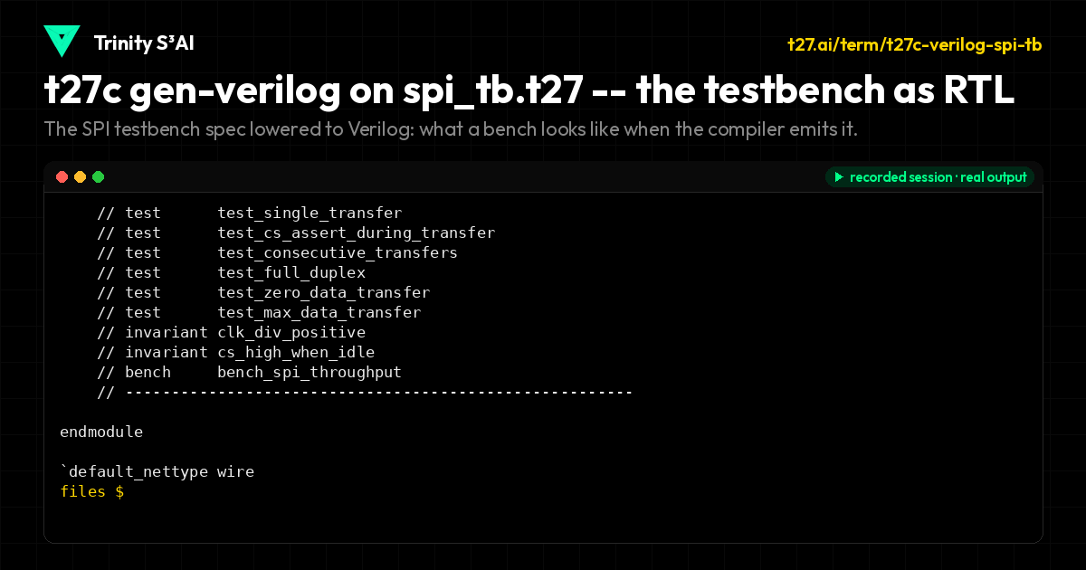
The SPI testbench spec lowered to Verilog: what a bench looks like when the compiler emits it.
specs/fpga/testbench/spi_tb.t27
// SPDX-License-Identifier: Apache-2.0
// t27/specs/fpga/testbench/spi_tb.t27
// SPI Master Testbench Specification
// Tests SPI transfer, clock generation, chip select, and mode handling
// phi^2 + 1/phi^2 = 3 | TRINITY

module SPI_Testbench {
    use fpga::spi::SPI_Master;

    const CLK_PERIOD : u32 = 20;
    const SIM_TIMEOUT : u32 = 10_000_000;
    const SPI_CLK_DIV : u32 = 4;

    var clk : bool = false;
    var rst_n : bool = false;
    var spi_start : bool = false;
    var spi_mosi_data : u32 = 0;
    var spi_miso_data : u32 = 0;
    var spi_cs_n : bool = true;
    var spi_sclk : bool = false;
    var spi_mosi : bool = false;
    var spi_miso : bool = false;
    var spi_done : bool = false;
    var spi_rx_data : u32 = 0;
    var spi_busy : bool = false;

    var test_passed : u32 = 0;
    var test_failed : u32 = 0;
    var bit_count : u32 = 0;

    fn tick() {
        clk = false;
        clk = true;
    }

    fn reset() {
        rst_n = false;
        tick();
        tick();
        rst_n = true;
        tick();
    }

    fn spi_transfer(tx_data : u32) -> u32 {
        spi_start = true;
        spi_mosi_data = tx_data;
        tick();
        spi_start = false;
        var timeout : u32 = 0;
        while !spi_done {
            tick();
            timeout = timeout + 1;
            if timeout > SIM_TIMEOUT {
                return 0xDEAD;
            }
        }
        return spi_rx_data;
    }

    test test_idle_state {
        reset();
        invariant spi_cs_n == true;
        invariant spi_sclk == false;
        invariant spi_busy == false;
    }

    test test_single_transfer {
        reset();
        var rx : u32 = spi_transfer(0xA5);
        invariant spi_done == true;
        invariant spi_busy == false;
        invariant spi_cs_n == true;
    }

    test test_cs_assert_during_transfer {
        reset();
        spi_start = true;
        spi_mosi_data = 0xFF;
        tick();
        invariant spi_busy == true;
        invariant spi_cs_n == false;
        spi_start = false;
    }

    test test_consecutive_transfers {
        reset();
        var rx1 : u32 = spi_transfer(0x01);
        var rx2 : u32 = spi_transfer(0x02);
        var rx3 : u32 = spi_transfer(0x03);
        invariant spi_done == true;
    }

    test test_full_duplex {
        reset();
        spi_miso = true;
        var rx : u32 = spi_transfer(0xAA);
        invariant rx != 0xDEAD;
    }

    test test_zero_data_transfer {
        reset();
        var rx : u32 = spi_transfer(0x00);
        invariant spi_done == true;
    }

    test test_max_data_transfer {
        reset();
        var rx : u32 = spi_transfer(0xFFFFFFFF);
        invariant spi_done == true;
    }


    invariant clk_div_positive : SPI_CLK_DIV > 0;
    invariant cs_high_when_idle : true;

    bench bench_spi_throughput {
        reset();
        var i : u32 = 0;
        while i < 100 {
            spi_transfer(i);
            i = i + 1;
        }
    }
}

// W696: the hardware boundary, DERIVED -- not chosen.
//
// T187 measured an exact equivalence over 617 specs: a module gets a data
// port iff the spec declares `on_comb` or `on_clock`. Without one the
// compiler emits `NO DATA PORTS -- this module cannot move a value across
// its boundary`, and synthesis optimises the whole thing away.
//
// The standing rule is that the default must NOT be guessed. Here no guess
// was made: `t27c entry-points` found exactly ONE function in this spec that
// takes a parameter, returns a value, has a body, and whose types all have a
// known width. With one candidate the choice is forced, so this forwards and
// invents nothing. 11 of 387 port-less specs qualified.
fn on_comb(tx_data: u32) -> u32 { return spi_transfer(tx_data); }
All lessons
Module 1 · What a bus is
Why a bus exists at all: a conversation on wires, framed and addressed, and who is allowed to talk.
Module 2 · UART
The two-wire bus with no clock: the frame, the divisor that sets the rate, and the status a driver polls.
Module 3 · SPI
The clocked conversation: four modes, a prescaler ladder, and a chip select per servant.
Module 4 · APB
The register bus: PSEL and PENABLE, strobes and wait states, and how many address bits a peripheral count costs.
Module 5 · AXI4
The five channels: address, data and response in both directions, lite or full, bursts and IDs.
Module 6 · Memory
What sits on the far side of every bus: memory maps, port kinds, and latency that a wait state must cover.
Module 7 · Bridges
Why designs grow more than one bus, and the packet bridge that moves work between them.
Module 8 · Ethernet
Frames, the frame check sequence, RGMII timing, and the pre-registered steps of a real bring-up.
Module 9 · The bench
The discipline that guards real hardware: who holds the IO, taking and giving the lock, and what runs next.