Строка create_clock
Вы узнаете
Что строка create_clock сообщает анализатору и какая спека её пишет.
Пока строки create_clock нет, анализатор не видит клока вовсе и ничего не хронометрирует: каждый путь без ограничений, каждый отчёт пуст. Строка называет порт, период и фронты формы волны. emitter_xdc.t27 — спека эмиттера, который пишет такие строки из спеки выводов, — её текст несёт create_clock -add -name среди строк, которые она выпускает. Нативный test-report на этой спеке в текущем дереве заблокирован, поэтому запись показывает то, что работает: t27c parse спеки, чисто, и grep, находящий её строки create_clock. Плеер компилирует спеку в браузере.
Попробуйте
В записи найдите строки create_clock, которые возвращает grep; затем в окне спеки найдите построитель строк эмиттера и скажите, чего нехватка create_clock делает с отчётом тайминга.
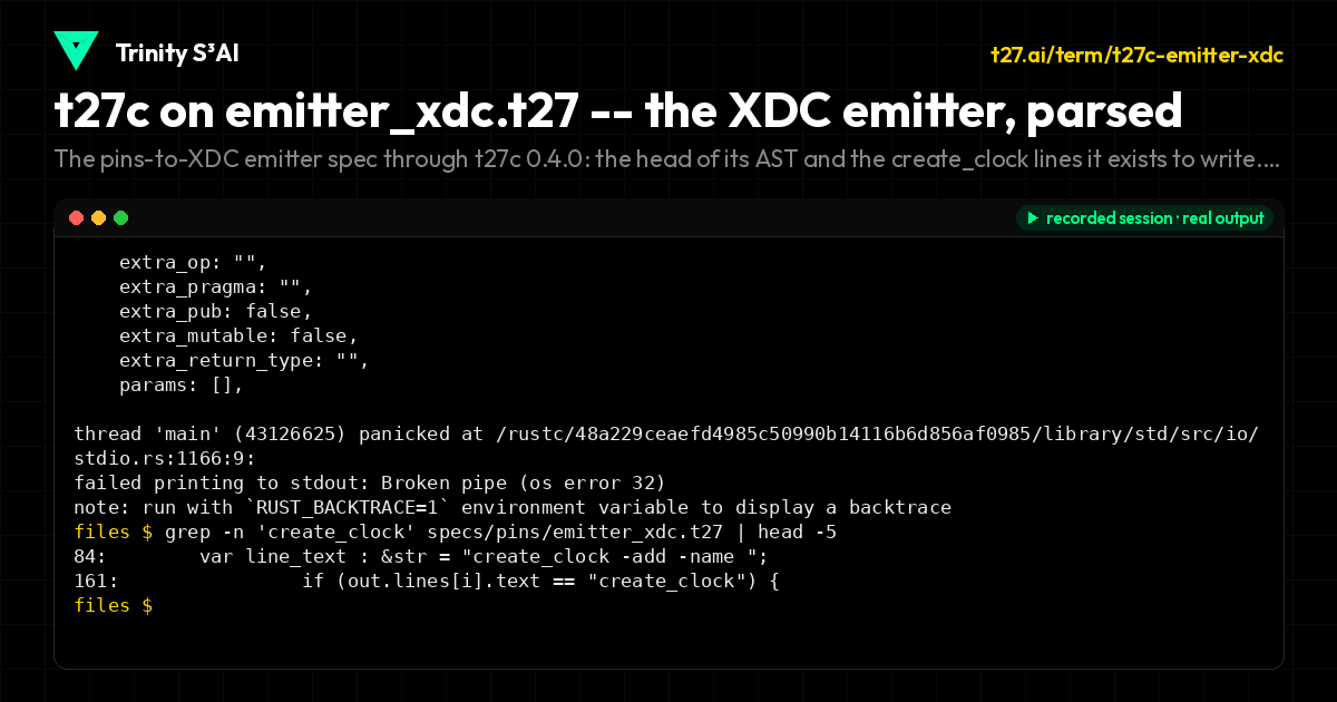
The pins-to-XDC emitter spec through t27c 0.4.0: the head of its AST and the create_clock lines it exists to write. Native test-report is blocked on this spec; parse is clean.
specs/pins/emitter_xdc.t27
// SPDX-License-Identifier: Apache-2.0
// t27/specs/pins/emitter_xdc.t27
// XDC Constraint Emitter from Pins IR
// Generates nextpnr-compatible XDC from Design/Binding/ClockDef
// Output format matches t27c fpga-build --minimal exactly
// phi^2 + 1/phi^2 = 3 | TRINITY

module EmitterXDC {
    use base::types;
    use base::ops;

    const HEADER_COMMENT : &str = "# nextpnr-compatible XDC";

    struct XDCLine {
        text : &str,
        is_comment : bool,
        is_empty : bool,
    }

    struct XDCOutput {
        lines : [512]XDCLine,
        count : usize,
    }

    fn empty_xdc() -> XDCOutput {
        return XDCOutput{
            .lines = [XDCLine{.text = "", .is_comment = false, .is_empty = true}; 512],
            .count = 0,
        };
    }

    fn add_line(out: XDCOutput, text: &str, is_comment: bool) -> XDCOutput {
        var result = out;
        if (result.count < 512) {
            result.lines[result.count] = XDCLine{
                .text = text,
                .is_comment = is_comment,
                .is_empty = false,
            };
            result.count = result.count + 1;
        }
        return result;
    }

    fn add_empty(out: XDCOutput) -> XDCOutput {
        var result = out;
        if (result.count < 512) {
            result.lines[result.count] = XDCLine{
                .text = "",
                .is_comment = false,
                .is_empty = true,
            };
            result.count = result.count + 1;
        }
        return result;
    }

    fn emit_pin(
        out: XDCOutput,
        package_pin: &str,
        iostandard: &str,
        port_name: &str,
    ) -> XDCOutput {
        var result = out;
        var line_text : &str = "set_property -dict { PACKAGE_PIN ";
        line_text = line_text + package_pin;
        line_text = line_text + "   IOSTANDARD ";
        line_text = line_text + iostandard;
        line_text = line_text + " } [get_ports ";
        line_text = line_text + port_name;
        line_text = line_text + "]";
        result = add_line(result, line_text, false);
        return result;
    }

    fn emit_clock(
        out: XDCOutput,
        port_name: &str,
        clock_name: &str,
        period_ns: u32,
        waveform_high_ns: u32,
    ) -> XDCOutput {
        var result = out;
        var line_text : &str = "create_clock -add -name ";
        line_text = line_text + clock_name;
        line_text = line_text + " -period ";
        var period_str : &str = "83.333";
        if (period_ns == 83) {
            period_str = "83.333";
        }
        line_text = line_text + period_str;
        line_text = line_text + " -waveform {0 ";
        var high_str : &str = "41.666";
        if (waveform_high_ns == 41) {
            high_str = "41.666";
        }
        line_text = line_text + high_str;
        line_text = line_text + "} [get_ports ";
        line_text = line_text + port_name;
        line_text = line_text + "]";
        result = add_line(result, line_text, false);
        return result;
    }

    fn emit_header(out: XDCOutput, design_name: &str) -> XDCOutput {
        var result = out;
        var hdr : &str = "# nextpnr-compatible XDC for ";
        hdr = hdr + design_name;
        result = add_line(result, hdr, true);
        return result;
    }

    fn qmtech_xc7a100t_minimal() -> XDCOutput {
        var out = empty_xdc();
        out = emit_header(out, "minimal design (prjxray-verified pins)");

        out = emit_pin(out, "E3", "LVCMOS33", "clk");
        out = emit_clock(out, "clk", "sys_clk", 83, 41);
        out = emit_pin(out, "C14", "LVCMOS33", "rst_n");
        out = emit_pin(out, "T14", "LVCMOS33", "uart_rx");
        out = emit_pin(out, "T15", "LVCMOS33", "uart_tx");

        out = emit_pin(out, "H17", "LVCMOS33", "led[0]");
        out = emit_pin(out, "K15", "LVCMOS33", "led[1]");
        out = emit_pin(out, "J13", "LVCMOS33", "led[2]");
        out = emit_pin(out, "N14", "LVCMOS33", "led[3]");
        out = emit_pin(out, "R18", "LVCMOS33", "led[4]");
        out = emit_pin(out, "U18", "LVCMOS33", "led[5]");
        out = emit_pin(out, "T13", "LVCMOS33", "led[6]");
        out = emit_pin(out, "T11", "LVCMOS33", "led[7]");

        return out;
    }

    fn arty_a7_minimal() -> XDCOutput {
        var out = empty_xdc();
        out = emit_header(out, "Arty A7 minimal (4 LEDs + UART + buttons)");

        out = emit_pin(out, "E3", "LVCMOS33", "clk");
        out = emit_clock(out, "clk", "sys_clk", 10, 5);
        out = emit_pin(out, "C12", "LVCMOS33", "rst_n");
        out = emit_pin(out, "A9", "LVCMOS33", "uart_tx");
        out = emit_pin(out, "C9", "LVCMOS33", "uart_rx");

        out = emit_pin(out, "R5", "LVCMOS33", "led[0]");
        out = emit_pin(out, "T5", "LVCMOS33", "led[1]");
        out = emit_pin(out, "T8", "LVCMOS33", "led[2]");
        out = emit_pin(out, "T9", "LVCMOS33", "led[3]");

        return out;
    }

    fn line_count(out: XDCOutput) -> usize {
        return out.count;
    }

    fn has_clk_constraint(out: XDCOutput) -> bool {
        var i : usize = 0;
        while (i < out.count) {
            if (!out.lines[i].is_empty and !out.lines[i].is_comment) {
                if (out.lines[i].text == "create_clock") {
                    return true;
                }
            }
            i = i + 1;
        }
        return false;
    }

    fn count_set_property_lines(out: XDCOutput) -> usize {
        var count : usize = 0;
        var i : usize = 0;
        while (i < out.count) {
            if (!out.lines[i].is_empty and !out.lines[i].is_comment) {
                count = count + 1;
            }
            i = i + 1;
        }
        return count;
    }

    test empty_xdc_has_zero_lines
        given out = empty_xdc()
        then line_count(out) == 0

    test add_line_increments_count
        given out = empty_xdc()
        and   out2 = add_line(out, "test line", false)
        then line_count(out2) == 1

    test add_comment_line
        given out = empty_xdc()
        and   out2 = add_line(out, "# comment", true)
        then line_count(out2) == 1 and out2.lines[0].is_comment == true

    test emit_pin_format
        given out = empty_xdc()
        and   out2 = emit_pin(out, "E3", "LVCMOS33", "clk")
        then line_count(out2) == 1

    test emit_pin_rst_n
        given out = empty_xdc()
        and   out2 = emit_pin(out, "C14", "LVCMOS33", "rst_n")
        then line_count(out2) == 1

    test emit_clock_format
        given out = empty_xdc()
        and   out2 = emit_clock(out, "clk", "sys_clk", 83, 41)
        then line_count(out2) == 1

    test emit_header_produces_comment
        given out = empty_xdc()
        and   out2 = emit_header(out, "test")
        then line_count(out2) == 1 and out2.lines[0].is_comment == true

    test qmtech_minimal_line_count
        given out = qmtech_xc7a100t_minimal()
        then line_count(out) == 13

    test qmtech_minimal_has_12_non_comment_lines
        given out = qmtech_xc7a100t_minimal()
        and   n = count_set_property_lines(out)
        then n == 13

    test qmtech_minimal_first_line_is_comment
        given out = qmtech_xc7a100t_minimal()
        then out.lines[0].is_comment == true

    test qmtech_minimal_second_line_is_clk_pin
        given out = qmtech_xc7a100t_minimal()
        then out.lines[1].is_comment == false and out.lines[1].is_empty == false

    test qmtech_minimal_third_line_is_clock
        given out = qmtech_xc7a100t_minimal()
        then out.lines[2].is_comment == false and out.lines[2].is_empty == false

    test qmtech_minimal_led_pins_count
        given out = qmtech_xc7a100t_minimal()
        and   n = count_set_property_lines(out)
        then n == 13

    test qmtech_minimal_has_all_12_signal_pins
        given out = qmtech_xc7a100t_minimal()
        then line_count(out) == 13

    test arty_a7_line_count
        given out = arty_a7_minimal()
        then line_count(out) == 9

    test arty_a7_starts_with_comment
        given out = arty_a7_minimal()
        then out.lines[0].is_comment == true

    test arty_a7_has_clk_and_clock
        given out = arty_a7_minimal()
        then line_count(out) == 9

    test arty_a7_4_leds
        given out = arty_a7_minimal()
        and   n = count_set_property_lines(out)
        then n == 9

    invariant empty_xdc_no_lines
        given out = empty_xdc()
        assert line_count(out) == 0

    invariant qmtech_minimal_has_exactly_13_lines
        given out = qmtech_xc7a100t_minimal()
        assert line_count(out) == 13

    invariant qmtech_minimal_starts_with_comment
        given out = qmtech_xc7a100t_minimal()
        assert out.lines[0].is_comment == true

    invariant qmtech_minimal_line_count_positive
        given out = qmtech_xc7a100t_minimal()
        assert line_count(out) > 0

    invariant line_count_never_exceeds_capacity
        given out = qmtech_xc7a100t_minimal()
        assert line_count(out) <= 512

    invariant arty_a7_line_count_positive
        given out = arty_a7_minimal()
        assert line_count(out) > 0 and line_count(out) == 9

    bench emit_pin_latency
        measure: nanoseconds to emit_pin(empty_xdc(), "E3", "LVCMOS33", "clk")
        target: < 500ns

    bench qmtech_minimal_gen_latency
        measure: nanoseconds to qmtech_xc7a100t_minimal()
        target: < 5000ns
}
Все уроки
Модуль 1 · Что такое тактовый сигнал
Один фронт, один мир: всё, что делит фронт тактового сигнала, делит и мир; период и джиттер настоящего фронта и место, где тактовый сигнал входит в плату.
Модуль 2 · Деревья тактового сигнала
Перекос и задержка прохождения, глобальная сеть буферов и ловушка стробирования клока логикой.
Модуль 3 · PLL и MMCM
Умножить и поделить один тактовый сигнал в другой, сдвинуть его фазу шагами VCO и какие тактовые сигналы анализатор считает родственными.
Модуль 4 · Сбросы
Ассертировать асинхронно, снимать синхронно: три вида сброса, конвейер снятия и дерево, которое растит сброс.
Модуль 5 · Метастабильность
Окно setup-hold, среднее время между отказами в целочисленной арифметике и два триггера, которые это чинят.
Модуль 6 · Пересечение многих бит
Почему двоичная шина рвётся, почему код Грея нет, и рукопожатие, переносящее импульс между мирами.
Модуль 7 · Асинхронный FIFO
Указатели, флаги и глубина: буфер, переносящий поток между двумя тактовыми сигналами.
Модуль 8 · Ограничения
Строки, сообщающие анализатору, что такое тактовый сигнал, какие пути не проверять и чему должны соответствовать выводы.
Модуль 9 · На плате
Отчёт CDC, одно пересечение, захваченное на триггерах, и дифф битстрима, замыкающий курс.