A correlator finds the frame
You will learn
How a Barker-13 correlator finds the start of a frame, and how many flipped chips it survives.
A frame starts with the 13 chips of the Barker code, whose correlation with itself is 13 lined up and at most 1 shifted. The modem spec bpsk.t27 pushes each received chip into a 13-chip window and correlates it; it locks at 9, well between sidelobe and peak. The widget runs those very functions on a stream of 32 chips: the peak stands at 13 where the preamble lines up, an inverted carrier gives -13, and every flipped chip in the window lowers the peak by 2.
Try it
Flip two chips of the preamble and check that it still locks; then find how many flips stop the lock.
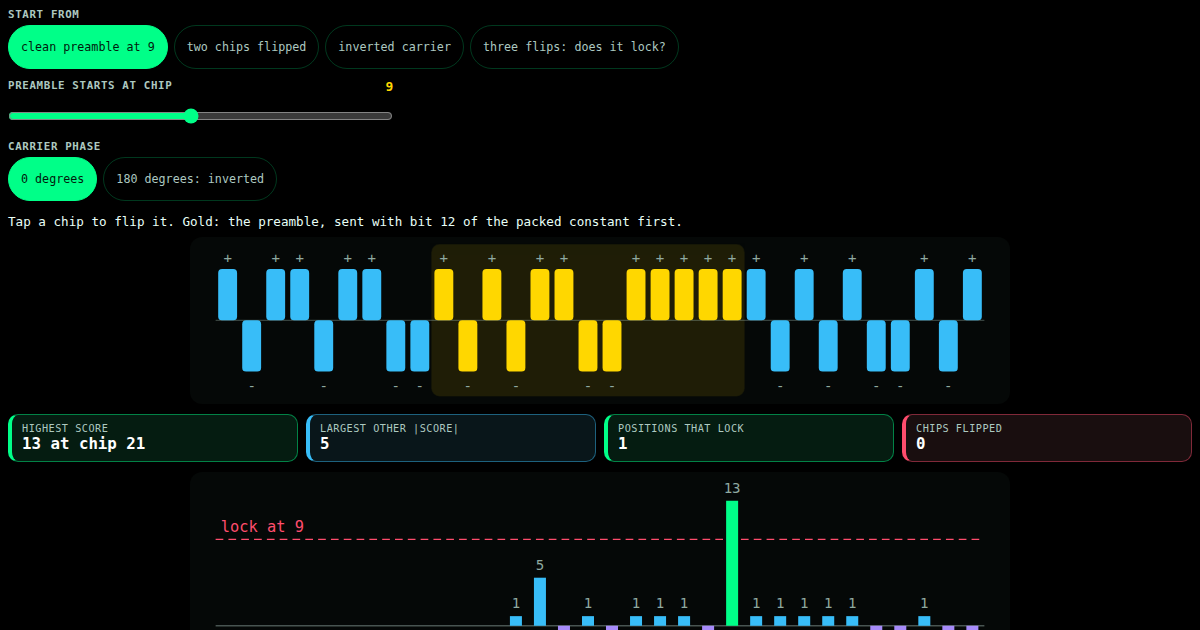
Slide a Barker-13 preamble through a stream of chips and watch the correlator peak at 13 where it lines up. Flip chips to add noise; see when the lock fails.
specs/fpga/bpsk.t27
// SPDX-License-Identifier: Apache-2.0
// t27/specs/fpga/bpsk.t27
// ZeroDSP BPSK modem core (TRI-NET 5.8 GHz mesh radio PHY).
// Byte -> +/-1 BPSK serializer with a Barker-13 preamble, plus an integer
// Barker-13 correlator + threshold for frame synchronization. Port of the
// trios-mesh Rust modem's synthesizable core to the t27 spec-first language.
// Datapath functions + state record only; clocking/ports are a backend concern.
// phi^2 + 1/phi^2 = 3 | TRINITY

module ZeroDSP_BPSK {
    use base::types;

    // Barker-13 chips packed into one 13-bit constant: bit k = chip k, with
    // 1 => +1 symbol and 0 => -1 symbol, chip 0 in the LSB. The chip order is
    // the transmit order [+1 +1 +1 +1 +1 -1 -1 +1 +1 -1 +1 -1 +1], matching the
    // Rust modem's BARKER13. Packing as bits (not an array) keeps the whole
    // module lowering to Verilog.
    // 5535 = 0b1010110011111, written in decimal so every reader of the constant
    // (the t27.ai widget gate reads declarations, it does not evaluate binary
    // literals) takes the same number.
    const BARKER13_BITS : u16 = 5535;
    const BARKER13_LEN  : usize = 13;
    const WINDOW_MASK   : u16 = 8191;   // 0x1FFF, 13 ones

    // Perfect autocorrelation peak is 13; the strongest Barker-13 sidelobe is 1.
    // Lock frame sync when the correlator sum crosses this coarse gate (the AEAD
    // tag downstream is the real validator, as in the Rust modem).
    const SYNC_THRESHOLD : i32 = 9;

    // Serial-line symbol codes.
    const SYM_POS : i8 = 1;
    const SYM_NEG : i8 = -1;

    // Frame layout in symbols: [preamble 13][length byte 8][payload len * 8].
    const PREAMBLE_SYMS : u32 = 13;
    const LENGTH_SYMS   : u32 = 8;
    const BITS_PER_BYTE : u32 = 8;

    // ---- Transmit serializer state ----
    // Held as top-level scalar registers (not a struct): the Verilog backend
    // names struct-field regs after the type but references them by the var
    // name, so flat scalars keep the generated RTL referencing declared signals.
    var tx_cur_byte   : u8   = 0;    // byte currently shifting out
    var tx_bit_index  : u8   = 0;    // next bit position 0..7 (LSB first)
    var tx_cur_symbol : i8   = 1;    // last emitted BPSK symbol (+1 / -1)
    var tx_sending    : bool = false; // true while a byte is in flight

    // ---- TX: one data bit -> one BPSK symbol (+1 / -1) ----
    // NB: use if/ELSE with a single assignment per path. The Verilog backend
    // lowers functions as sequential assignments (no early return), so a bare
    // `if {..} return X` fall-through would always take the last statement.
    fn bit_to_symbol(bit: u8) -> i8 {
        if (bit == 1) {
            return SYM_POS;
        } else {
            return SYM_NEG;
        }
    }

    // Load a new byte into the serializer; refuses while a byte is in flight.
    fn tx_load(byte: u8) -> bool {
        if (tx_sending) {
            return false;
        } else {
            tx_cur_byte  = byte;
            tx_bit_index = 0;
            tx_sending   = true;
            return true;
        }
    }

    // Emit the BPSK symbol for the current bit (LSB first) and advance.
    fn tx_next_symbol() -> i8 {
        if (!tx_sending) {
            return SYM_POS;
        } else {
            tx_cur_symbol = bit_to_symbol((tx_cur_byte >> tx_bit_index) & 1);
            tx_bit_index  = tx_bit_index + 1;
            if (tx_bit_index >= 8) {
                tx_sending = false;
            }
            return tx_cur_symbol;
        }
    }

    // ---- RX: Barker-13 correlation ----
    // Per-chip contribution: +1 when the window bit matches the Barker bit,
    // -1 otherwise (equivalent to symbol * chip for +/-1 BPSK). Flat helper so
    // no local temporaries are needed inside `correlate`.
    fn chip_contrib(win: u16, k: usize) -> i32 {
        if (((win >> k) & 1) == ((BARKER13_BITS >> k) & 1)) {
            return 1;
        } else {
            return -1;
        }
    }

    // Full 13-tap correlation, unrolled (a flat sum lowers cleanly to Verilog).
    fn correlate(win: u16) -> i32 {
        return chip_contrib(win, 0)
             + chip_contrib(win, 1)
             + chip_contrib(win, 2)
             + chip_contrib(win, 3)
             + chip_contrib(win, 4)
             + chip_contrib(win, 5)
             + chip_contrib(win, 6)
             + chip_contrib(win, 7)
             + chip_contrib(win, 8)
             + chip_contrib(win, 9)
             + chip_contrib(win, 10)
             + chip_contrib(win, 11)
             + chip_contrib(win, 12);
    }

    // Advance the sliding window by one hard-decided symbol bit (shift left,
    // insert at LSB, keep 13 bits). Pure: takes the current window and returns
    // the next one, so it lowers cleanly to combinational Verilog.
    fn rx_push(win: u16, bit: u8) -> u16 {
        return ((win << 1) | bit) & WINDOW_MASK;
    }

    // Frame sync locked when the correlator peak crosses the threshold.
    fn sync_locked(sum: i32) -> bool {
        return sum >= SYNC_THRESHOLD;
    }

    // Total symbols in a framed packet with `payload_len` payload bytes.
    fn frame_symbol_count(payload_len: u32) -> u32 {
        return PREAMBLE_SYMS + LENGTH_SYMS + payload_len * BITS_PER_BYTE;
    }

    // ---- TDD blocks (L4): mirror the Rust modem's unit tests ----

    // Aligned preamble gives the perfect autocorrelation peak of 13.
    test barker_autocorrelation_peak
        given peak = correlate(BARKER13_BITS)
        then peak == 13

    // A 180-degree channel inversion flips every chip -> negative peak -13,
    // which is how the modem detects and resolves phase inversion.
    test inverted_barker_is_negative_peak
        given anti = correlate((~BARKER13_BITS) & WINDOW_MASK)
        then anti == -13

    // Off-peak windows sit far below the peak (|value| <= 5 here).
    test off_peak_all_zeros
        given s = correlate(0)
        then s == -5

    test off_peak_all_ones
        given s = correlate(WINDOW_MASK)
        then s == 5

    // BPSK bit -> symbol mapping.
    test bit1_maps_to_plus_one
        given s = bit_to_symbol(1)
        then s == 1

    test bit0_maps_to_minus_one
        given s = bit_to_symbol(0)
        then s == -1

    // Serializer emits LSB first: 0x01 -> first symbol +1.
    test tx_serializes_lsb_first
        given tx_load(0x01)
        and s = tx_next_symbol()
        then s == 1

    // 0x02: bit0=0 -> -1, bit1=1 -> +1.
    test tx_second_bit_is_plus_one
        given tx_load(0x02)
        and tx_next_symbol()
        and s = tx_next_symbol()
        then s == 1

    // Sliding window shifts a bit in at the LSB.
    test rx_window_shifts_in
        given w = rx_push(0, 1)
        then w == 1

    // Window keeps only 13 bits (the shifted-out bit is masked away).
    test rx_window_keeps_13_bits
        given w = rx_push(8191, 1)
        then w == 8191

    // Threshold gate.
    test sync_locks_at_peak
        given locked = sync_locked(13)
        then locked == true

    test sync_open_below_threshold
        given locked = sync_locked(5)
        then locked == false

    // Smallest frame (empty payload) = 13 preamble + 8 length = 21 symbols.
    test smallest_frame_is_21_symbols
        given n = frame_symbol_count(0)
        then n == 21

    // ---- Invariants ----

    // The lock gate must sit between the worst sidelobe (1) and the peak (13).
    invariant threshold_within_peak
        assert SYNC_THRESHOLD <= 13

    invariant threshold_above_sidelobe
        assert SYNC_THRESHOLD > 1

    invariant barker_length_is_13
        assert BARKER13_LEN == 13

    invariant window_mask_covers_13_bits
        assert WINDOW_MASK == 8191
}
All lessons
Module 1 · Adding numbers
Why addition is slow: the carry that walks up the word, the dedicated chain in every slice, prefix networks and carry-save trees.
Module 2 · Multiplying
A product is a sum of shifted copies; Booth recoding halves them, and the DSP48E1 slice does the rest in one block.
Module 3 · Fixed point
Where the binary point sits, what rounding does to a value and to its average, and what each bit of a quantizer buys.
Module 4 · Functions in hardware
Sine, cosine, angle and length from shifts and adds, and when a table is the better answer.
Module 5 · Signals and sampling
What sampling does to a frequency, how an oscillator is built from an adder, and what a DFT bin measures.
Module 6 · FIR filters
The moving average, a windowed-sinc design with integer taps, and folding the taps onto DSP slices.
Module 7 · Multirate
Lowering the sample rate without folding noise in: decimation, the CIC filter and the polyphase form.
Module 8 · The FFT
N log N instead of N^2: butterflies, the bit-reversed input order and the bits each stage adds.
Module 9 · On the bench
From the arithmetic to the board: a correlator from the modem spec, a budget of slices and timing, and the capstone filter.